Downloads
Executable for the map editor - exactly the same as in part 21 (Windows 32bits)
Executable for the game (Windows 32bits)
Before you try to compile the code go to the "Projects" tab on the left menu, select the "Run" settings for your kit,
and set the "Working directory" to the path of "editor\data" for the editor or "game\data" for the game.
The objects database
I will be quite different of the one we wrote in the last part for the editor, that contained only names.
We will probably have to change that later to use the same file in both places, but for now, we'll use 2 different files
for a while.
This will surely be the largest database of the game, as it will define all the characteristics of the 170 objects.
But we will start with a simple version and we will add the various characteristics as we will need them in the future
parts.
So let's see what datas we need to display our objects on the ground:
		<?xml version="1.0" encoding="utf-8"?>
		<items>
			<!-- ======================== Weapons ======================== -->
			<!-- EYE OF TIME -->
			<item name="ITEM001">
				<category>Weapon</category>
				<floor_image>00W_Ring.png</floor_image>
			</item>

			<!-- STORMRING -->
			<item name="ITEM002">
				<category>Weapon</category>
				<floor_image>00W_Ring.png</floor_image>
			</item>

			[...]
		</items>
		<?xml version="1.0" encoding="ISO-8859-1"?>
		<texts>
			[...]
			<text id="ITEM001">EYE OF TIME</text>
			<text id="ITEM002">STORMRING</text>
			<text id="ITEM003">TORCH</text>
			<text id="ITEM004">FLAMITT</text>
			[...]
		</texts>
- Weapon: Every object that you can put in your hand to hit the ennemies. It does not only contains swords and axes,
but also throwing weapons, rings that can cast spells and torches. - Armor: Everything from fabric clothes to plate armors. Also including helms and shields.
- Scroll: Only one type of scrolls in this game.
- Potion: Everything in a flask. That can be potions, bombs, and even empty flasks, or flasks full of water.
- Container: There is only one type of container in this game: the chest.
- Misc: Every other object, including keys, coins, necklaces and lots of various things.
In the future it may be useful to define the additionnal parameters. I.e. a weapon will have an "attack" value, an armor will have
a "defense" value, a scroll will have a text, and so on.
Finally, each object in the database contains the name of the image used to draw it on the floor.
You can find them in "data/gfx/3DView/items_floor/", I gave them a number and sorted them by category:
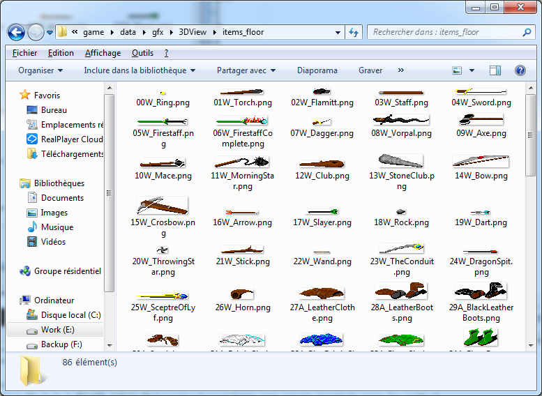
The graphists did not draw an image for each object, so for the 170 objects there are only 86 different images.
Some objects share the same graphics - i.e. the plate armors, most of the swords, most of the potions...
This file is read by readObjectsDB() in "objects.cpp" a new source file for all the functions related to objects.
The datas are stored in the mObjectInfos vector.
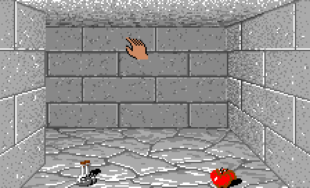
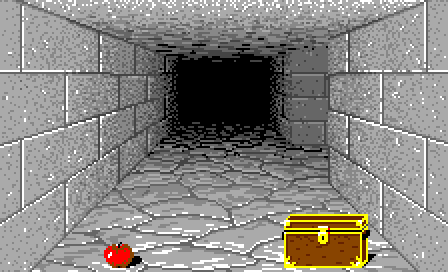
Positions of the objects
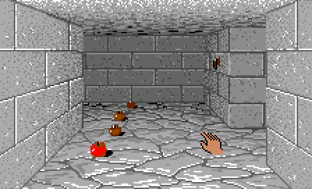
They probably used a big coordinates table for every possible position.
I did not want to write another big table in the code, so I found a formula to get roughly the same positions:
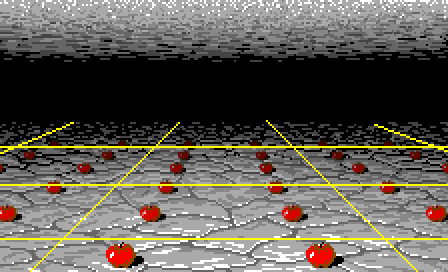
It took me more time that I expected.
Normally to get a perspective effect like that, you have to divide the coordinates by the "depth" and add a few
coefficient to scale the thing.
But, as I said before, this game is full of perspective errors, so I ended up with a weird formula, with a 0.9 corrrection
factor out of nowhere.
Here it is:
		CVec2 CObjects::getObjectPos(CVec2 tablePos)
		{
			CVec2   pos;
			pos.x = 250 * (tablePos.x - 4.5) / (8.5 - tablePos.y) + 112;
			pos.y = 310 / (8.5 - 0.9 * tablePos.y) + 66;
			return pos;
		}
add the monsters.
The front and back rows
may be hidden behind a door.
So we have 2 functions, one for the back row - the farthest from us - and one for the front row - the nearest.
Here is the function for the back row:
		void CObjects::drawBackRow(QImage* image, CVec2 mapPos, CVec2 tablePos)
		{
			CVec2   pos1, pos2;

			switch (player.dir)
			{
				case 0: // up
					pos1 = CVec2(0, 0);
					pos2 = CVec2(1, 0);
					break;

				case 1: // left
					pos1 = CVec2(0, 1);
					pos2 = CVec2(0, 0);
					break;

				case 2: // down
					pos1 = CVec2(1, 1);
					pos2 = CVec2(0, 1);
					break;

				case 3: // right
					pos1 = CVec2(1, 0);
					pos2 = CVec2(1, 1);
					break;
			}

			drawObjectsStack(image, mapPos * 2 + pos1, tablePos * 2 + CVec2(0, 0));
			drawObjectsStack(image, mapPos * 2 + pos2, tablePos * 2 + CVec2(1, 0));
		}
in a tile.

In this function, there are 4 differents cases where we set coordinates based on the direction the player is looking at.
This image will explain you where these coordinates comes from:
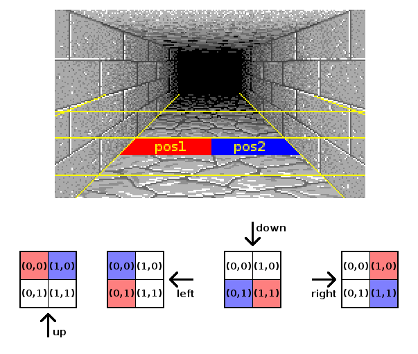
The function for the front row is the same except for the coordinates.
Drawing the objects
		void CObjects::drawObjectsStack(QImage* image, CVec2 mapPos, CVec2 tablePos)
		{
			if (tablePos.y < 1 ||
				tablePos.y > (WALL_TABLE_HEIGHT - 1) * 2)
				return;

			CObjectStack*   stack = map.findObjectsStack(mapPos);

			if (stack != NULL)
			{
				for (size_t i = 0; i < stack->getSize(); ++i)
				{
					int type = stack->getObject(i).getType();

					if (type != 0)
					{
						// get object image
						CObjectInfo object = mObjectInfos[type - 1];
						QImage  objectImage = fileCache.getImage(object.floorImage.toLocal8Bit().constData());

						// get object position and add a pseudo random value
						CVec2   pos = getObjectPos(tablePos);
						pos.x += ((mapPos.x - mapPos.y + i) * 53) % 7 - 3;
						pos.y += (i < 4 ? i : 3);

						// compute the scale based on the reference position (the nearest)
						CVec2   pos0 = getObjectPos(CVec2(WALL_TABLE_WIDTH, (WALL_TABLE_HEIGHT - 1) * 2));
						CVec2   pos1 = getObjectPos(CVec2(WALL_TABLE_WIDTH, tablePos.y));
						float   scale = (float)(pos1.x - 112) / (float)(pos0.x - 112);

						// scale the object in a temporary image
						QImage  scaledObject(objectImage.size() * scale, QImage::Format_ARGB32);
						scaledObject.fill(QColor(0, 0, 0, 0));
						graph2D.drawImageScaled(&scaledObject, CVec2(), objectImage, scale);

						// darken the object based on it's distance
						float shadow = ((WALL_TABLE_HEIGHT - 1) * 2 - tablePos.y) * 0.13f;
						graph2D.darken(&scaledObject, shadow);

						// draw the object on screen
						pos -= CVec2(scaledObject.size().width() / 2, scaledObject.size().height() - 1);
						graph2D.drawImage(image, pos, scaledObject, 0, false, QRect(0, 33, MAINVIEW_WIDTH, MAINVIEW_HEIGHT));
					}
				}
			}
		}
Before drawing the object, we have to substract half of the width and the full height of the image from the position,
so that the position we computed in getObjectPos() correspond to the bottom middle of the object.

We do this, because, as the objects are laying on the ground, two different objects should be aligned by their bottom
Finally there is a last little trick that you can see at the beginnig of the loop: we add a little random to the position
to avoid that objects completely overlaps when there are several times the same object in a stack.