The code in this article was written using Code::Blocks and SDL 2.
You can read
here a guide to install this software.
Although it is based on SDL, I don't use its functions directly. I have written a small library with a few basic
functions to ease the understanding and the portability to another language.
You can read more about this lib
here.
In this article I use the Targa functions from
here.
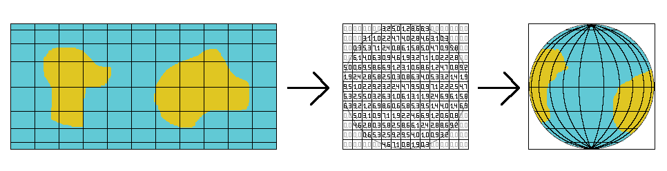
In this article we will map a texture on a sphere and animate it but completely in 2D.
The trick is to precalculate a table that contains the coordinates in the texture for each pixel on the screen.
The texture we will use is a Lambert cylindrical equal-area projection.
That means you can roll it as a cylinder wrapping the sphere. And each point on the sphere is projected on the
cylinder along a horizontal line.
In fact we will use some of the images from
this wikipedia page to display the Earth.
All along this article, we will use the dimensions of this texture. So we will name them imageWidth and imageHeight.
Now the hardest part of this problem is to compute the values in the coordinates table.
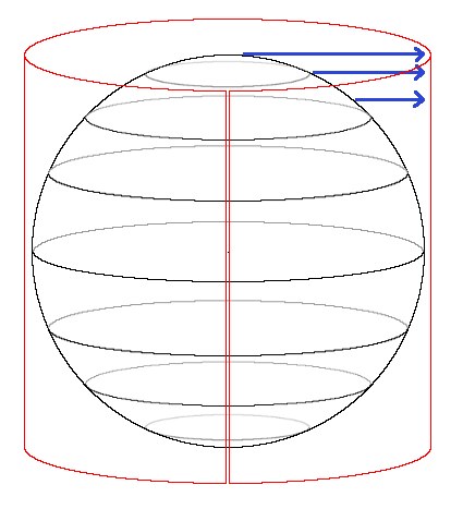
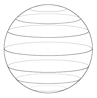
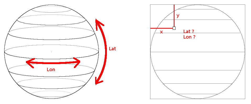
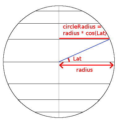
Now think about the sphere in three dimensions.
In this image I drew some parallels as a reference.
We will look at it with our eyes in the plane of the equator.
We will use an othographic projection, so there will not be deformations due to perspective, and we will always see
one half of the sphere.
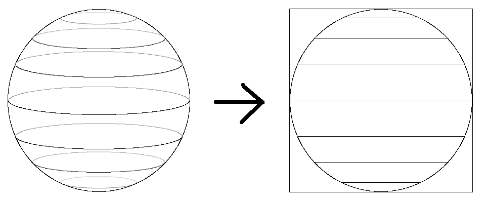
With these rules the parallels will appear as lines on the screen.
As the texure is rolled as a cylinder has the same height as the sphere, the image on the screen will have the same
height of imageHeight.
As the image on the screen is a circle, its width is imageHeight too.
And the coordinates table will have the same dimensions, because each coordinate corresponds to a pixel on the
screen.
On Earth we define our position with the latitude and the longitude which are two angles.
Now in the other hand, when we will fill our coordinates table, we will loop along x and y.
In order to find the coordinates on the texture, we will need to compute the latitude and the longitude of each
pixel on the screen.
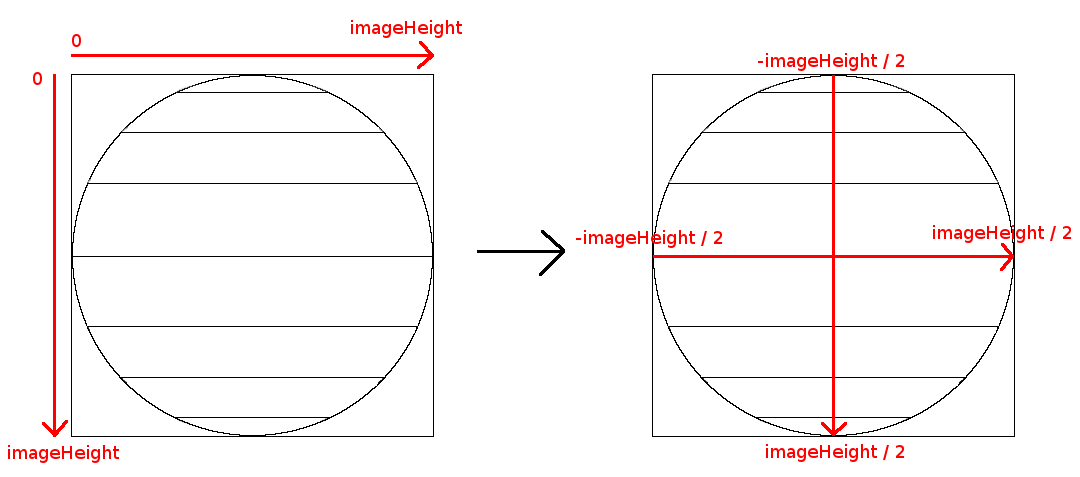
But before going further we will adapt our x and y coordinates.
When you think about an image on the screen, the coordinates start at the top left and the increase towards the
right and the bottom.
For our square image, the x and y would vary between 0 and imageHeight.
But when you work with circles or spheres it is easier to position the points relative to their centers.
So we will shift our coordinates so that they go between -imageHeight/2 and imageHeight/2.
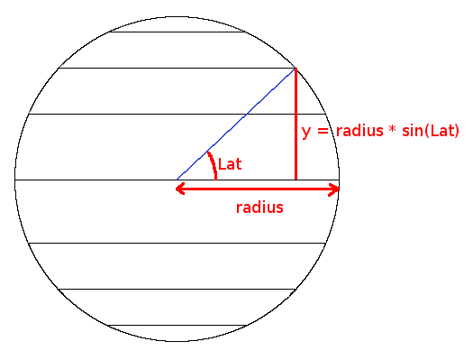
Finding the latitude of a point is quite easy.
The sphere will appear on our screen as a circle with a radius of imageHeight/2.
If you look at a point from the side of this circle, you will see that it appears in a triangle where we know
2 sides:
The radius which is the longest side, and the y coordinate.
If you read my article about
circles, you will immediately understand that:
y = radius * sin(latitude);
From this formula we can derive that:
sineLatitude = sin(latitude) = y / radius;
and
latitude = asin(sineLatitude);
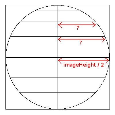
As we found the latitude from the y coordinate, we will find the longitude from the x coordinate.
But here have a little problem. The maximum and minimum values of x varies with the latitude.
If you look at this image, you see that these limits depends on the parallel.
If we are on the equator we know the radius of the parallel but if we are at another latitude we have to calculate
it.
Now we can draw a figure that looks like the one for the latitude, except that we are looking at the horizontal
coordinate.
From this image we can deduce that:
circleRadius = radius * cos(latitude)
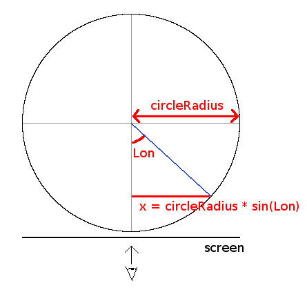
Now that we know the radius of the parallel where our point is, let's turn everything so that we look at the north
pole of the sphere.
In this position, the screen is a line at the bottom of the figure.
We are now seeing our parallel as the circle for which we calculated the radius.
The x coordinate will give us a point on this circle, and looking at this figure we get another equation
containing the longitude.
So we have:
x = circleRadius * sin(longitude)
From this we can derive:
sineLongitude = sin(longitude) = x / circleRadius
and
longitude = asin(sineLongitude)
Computing the texture coordinates
Now, for each pixel on the screen we know its x and y coordinates, and its latitude and longitude on the sphere.
With all these datas we will now have to find the corresponding x, and y coordinates in the texture.
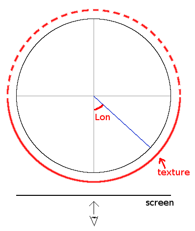
Let's look at the sphere from the top again. With the texture wrapped around it as a cylinder.
The longitude we computed goes from -π/2 to π/2. As we don't like negative coordinates we will add π/2 to
it. So it will go from 0 to π.
We see on the figure that this angle corresponds to the texture's x coordinate.
But as we only see one half of the sphere, we can conclude that:
textureX = (longitude * imageWidth / 2) / M_PI
Now for the y coordinate, let's look again at this figure that we had at the beginning:
We see that each point of the sphere is projected along a horizontal line and that the height of the texture is
the same as the height of the sphere.
So the texture's y coordinate will simply be the pixel's y coordinate:
textureY = y
Now that you read this lengthy explanations let's code that.
We will begin by declaring imageWidth and imageHeight.
		#include <stdio.h>
		#include <stdlib.h>
		#include "main.h"
		#include "Graphics.h"
		#include "System.h"
		#include "math.h"
		#include "formats/TGA.h"

		int imageWidth;
		int imageHeight;
The coordinates table will be called mapPos.
It's an array of structures that contain a x and a y coordinates.
		struct SMapPos
		{
			unsigned short int  x, y;
		};

		SMapPos* mapPos;
The initMapPos function is where we will fill this array.
We start by allocating memory for it.
		void initMapPos()
		{
			mapPos = (SMapPos *)malloc(imageHeight * imageHeight * sizeof(SMapPos));

			float radius = (float)imageHeight / 2;
Then we loop over each pixel, and we get a pointer on the current cell in the array.
			for (int y = 0; y < imageHeight; y++)
				for (int x = 0; x < imageHeight; x++)
				{
					SMapPos* pos = &mapPos[y * imageHeight + x];
Here we will apply the formulas we found to compute the longitude and the latitude of the current pixel.
					float centeredX = (float)x - radius;
					float centeredY = (float)y - radius;

					float sineLatitude = centeredY / radius;
					float latitude = asin(sineLatitude);

					float circleRadius = radius * cos(latitude);
					float sineLongitude = centeredX / circleRadius;
Just before computing the longitude, we check its sine to see if the pixel is inside the circle that will picture
the sphere on the screen.
					// inside circle ?
					if (sineLongitude >= -1.0f && sineLongitude <= 1.0f)
					{
						float longitude = asin(sineLongitude) + M_PI / 2;
Now we compute the texture coordinates from x, y, latitude and longitude and store them in the current cell of
mapPos.
						pos->x = (longitude * imageWidth / 2) / M_PI;
						pos->y = y;
					}
If the pixel was not inside the circle, we simply put the coordinates (0, 0).
					else
					{
						pos->x = 0;
						pos->y = 0;
					}
				}
		}
In the main function, we first load the texture and initialize the screen with its dimensions.
		int main(int argc, char* argv[])
		{
			// init the window
			Color* image = tga.load("earth.tga", &imageWidth, &imageHeight);

			gfx.init("Earth", imageHeight, imageHeight);
			gfx.init2D();
			gfx.clearScreen(Color(0, 0, 0, SDL_ALPHA_OPAQUE));
Then we fill mapPos. As we said it's a precomputed table, so initMapPos needs only to be called one time.
			// initialise the table
			initMapPos();
In the main loop, to draw the sphere, we loop over each pixel, we get the coordinates in the texture from mapPos,
and we draw the pixel from the texture on the screen.
			while (sys.isQuitRequested() == false)
			{
				// draw the sphere
				for (int y = 0; y < imageHeight; ++y)
					for (int x = 0; x < imageHeight; ++x)
					{
						SMapPos* pos = &mapPos[y * imageHeight + x];
						int px = pos->x;
						int py =  pos->y;
						Color col = image[py * imageWidth + px];

						gfx.setPixel(x, y, col);
					}
Then as usual we render, handle the events, and then quit at the end.
				// render and handle events
				gfx.render();
				sys.processEvents();
				sys.wait(16);
			}

			gfx.quit();
			delete[] image;
			free(mapPos);

			return EXIT_SUCCESS;
		}

		Download source code
		Download executable for Windows
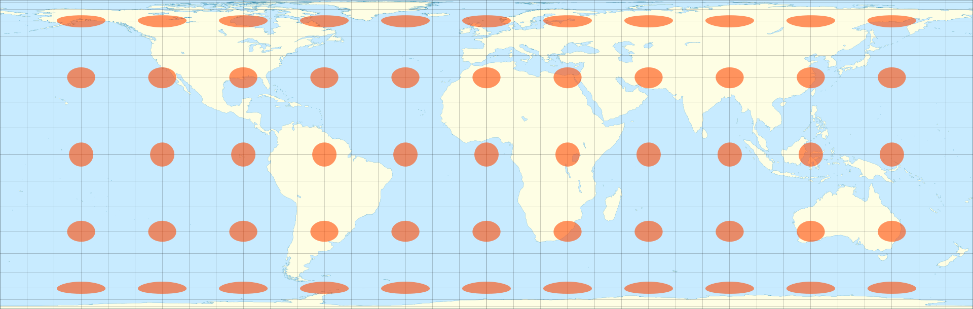
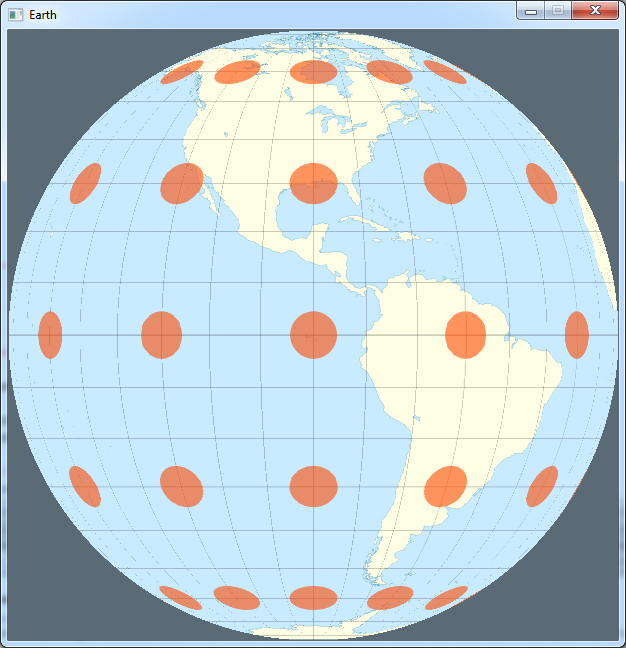
To test if our calculations were right, I used this image from the wikipedia page:
By Eric Gaba (
Sting -
fr:Sting) -
Own workData : U.S. NGDC World Coast Line (public domain),
CC BY-SA 4.0,
Link
The orange ellipses on it are the Tissot's indicatrix that show the distortions due to the projection of the Earth
on the map.
If our calculations were right, they should appear as circles, all of the same size, on the surface of the sphere.
And it seems to work.
Now to check if our calculations were right all around the sphere, we will make it rotate.
The beauty of the technique we used is that we don't need to re-compute the coordinates table for each angle of
rotation.
We will only "offset" the x position of the texture.
To do that we need a scroll variable, that we will initialize outside the main loop.
			// initialise the table
			initMapPos();
			int scroll = 0;

			while (sys.isQuitRequested() == false)
Then, when we draw the sphere we will add this variable to the x coordinate we read from the table.
The "% imageWidth" is here to make sure that the result stays between 0 and imageWidth-1.
			SMapPos* pos = &mapPos[y * imageHeight + x];
			int px = (pos->x + scroll) % imageWidth;
			int py =  pos->y;
And finally, in the main loop, we need to decrement it to make the sphere turn in the right direction.
If it is negative we add imageWidth to it, again to stay between 0 and imageWidth-1.
			scroll--;
			if (scroll < 0)
				scroll += imageWidth;

			// render and handle events

		Download source code
		Download executable for Windows
The background flashes a little bit because it follows the first line of the texture.
Remember we set the coordinates (0, 0) in the table for the points outside the circle, but now we add scroll.
Anyways we can see that the orange circles have always the same size all along the rotation.
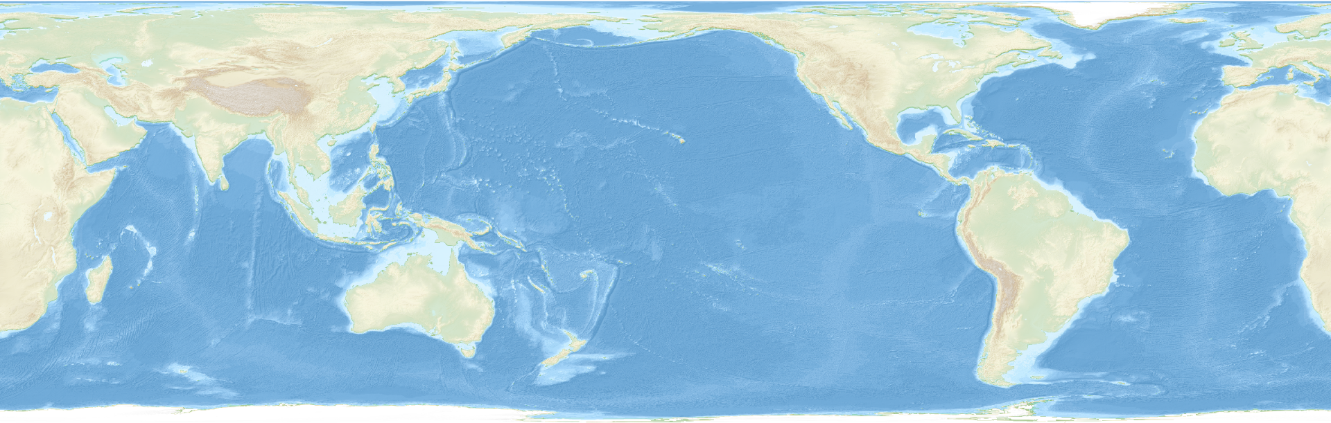
Now for something a bit more realistic let's use another image of the Wikipedia page:
By
Uwe Dedering -
Own work,
CC BY-SA 3.0,
Link
		Download source code
		Download executable for Windows
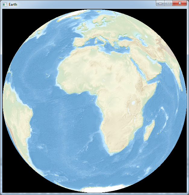
Here is the result:
You may find that we don't really feel the volume of the Earth. So let's try to add time zones to see how it looks.
In the main loop, just before we draw the pixel we will add this code:
		const float hour = imageWidth / 24.0f;
		int timezone = px / hour;
		if (timezone % 2)
		{
			col.r *= 0.5;
			col.g *= 0.8;
		}

		gfx.setPixel(x, y, col);

		Download source code
		Download executable for Windows
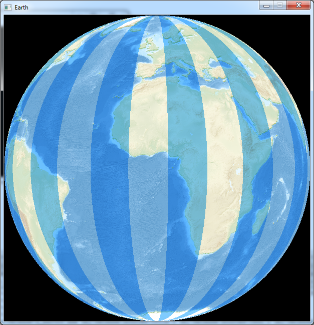
We divide the texture's x coordinate by 1/24th of the texture's width, and if the result is odd, we slightly modify
the color.
Now the earth looks a bit like a beach ball.
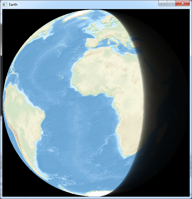
Now instead of time zones, let's display a shadow on a part of the earth.
Instead of the previous code, before we draw the pixel, we will write that:
		const int shadow = (imageWidth * 1 / 3);

		if (pos->x > shadow)
		{
			col.r = col.r / (1 + (pos->x - shadow) / 8.0f);
			col.g = col.g / (1 + (pos->x - shadow) / 8.0f);
			col.b = col.b / (1 + (pos->x - shadow) / 8.0f);
		}

		gfx.setPixel(x, y, col);

		Download source code
		Download executable for Windows
The variable shadow is the position where the shadow begins.
The calculations inside the "if" are here to make a gradient instead of an abrupt shadow.
Notice that we use pos->x instead of px, so we do not take into account the scroll variable and the shadow will not
rotate with the Earth.
And this is what it looks like:
Now this shadow is not really accurate because it does not take into account the axial tilt of the Earth...